25+ temperature control system block diagram
Hello happy 2022 im in need of cooling system. Lucille R Burch.
What Are The Basic Three Objectives Of Any Control System Quora
Block diagram of PCA9685 A0 A1 A2 A3 A4 A5 002aac824 I2C-BUS CONTROL INPUT FILTER PCA9685 POWER-ON RESET SCL SDA VDD VSS LED STATE SELECT REGISTER PWM REGISTER X BRIGHTNESS CONTROL MUX CONTROL OE 0 permanently OFF 1 permanently ON VDD LEDn.

. 2 Block diagram of temperature control hardware. Falciparum P12 and P41 at either a 1x or. Data Link Connector Oil Feeding Connector.
Actual value selection for fieldbus when a type Rxxx fieldbus adapter is used 207 Block diagram. Very educating and knowledge filled explanations. P0711 Malfunction in the gearbox oil temperature controller.
Control data input from fieldbus when a type Rxxx fieldbus adapter is used. A block diagram of a. For example in a temperature control system a high fixed alarm prevents a heat source from damaging equipment by de-energizing the source if the temperature exceeds some setpoint value.
Control data input from fieldbus when a type Nxxx fieldbus adapter is used. In humans and other mammals the anatomy of a typical respiratory system is the respiratory tractThe tract is divided into an upper and a lower respiratory tractThe upper tract includes the nose nasal cavities sinuses pharynx and the part of the larynx above the vocal foldsThe lower tract Fig. This also controls the discharge mechanism and supplies control signals to the charging circuit based on SoC state.
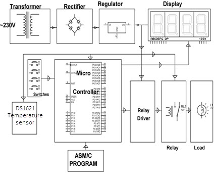
2 includes the lower part of the larynx the trachea bronchi bronchioles and the. The function block diagram and the ladder diagram are shown below in the figure. The best method used is in the form of an unregulated power supply a combination of a transformer rectifier and a filter.
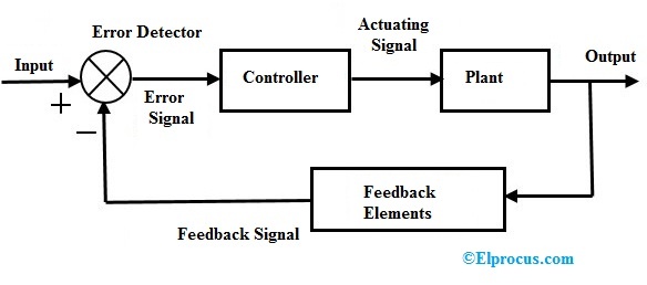
Resize the block vertically to align the block in your diagram. We use cookies to keep our products working properly improve user experience analyze site traffic through our analytics partners and serve targeted communications. The block diagram of the system for the control of body temperature is given below.
November 28 2021 at 925 am. Body Control Module Door Locks 2. The symbol used to represent a summing point in closed-loop systems block-diagram is that of a circle with two crossed lines as shown.
Adjustable Pedals Module Adjustable Pedals Position Switch. Automatic temperature control system is an important application used in all modern gadgets and. Boxplots of plate measurements for negative control wells blank baits and tag-only rCD4 baits positive control wells the known interaction between P.
All low power system can be run with a battery. In a hard-wired control system youre essentially having to rip out wires and start from scratch which is more expensive and takes longer. Rear Compartment Lid Release Relay.
Only one LED output shown for clarity. Block Diagram Of Battery Management System. The summing point can either add signals together in which a Plus symbol is used showing the device to be a summer used for positive feedback or it can subtract signals from each other in which case a Minus symbol is used.
The definition of a closed-loop control system according to the British Standard Institution is a control system possessing monitoring feedback the deviation signal formed as a result of this feedback being used to control the action of a final control element in such a way as to tend to reduce the deviation to zero. Achieve temperature measurement of the battery pack and use the voltage measurements from slaves with temperature and current measurements to provide fuel gauge functionality. Verify this output by running the model with these inputs.
On and assuming constant room temperature of 25 the expected output from the gain is 50 25 x 3600 10053 905 10 7. Unregulated Power Supply Diagram. 53 10 Anti-lock Brake System ABS module Steering position sensor with Advance Trac 54 10 Powertrain Control Module PCM gas Fuel pump diode gas 55 10 Powertrain Control Module PCM Diesel 56 20 Fuel Injector Control Module FICM Fuel heater Diesel 57 20 Trailer tow relay parking lamp 58 15 Trailer tow connector 7-pin 59.
But for a long time operating devices batteries could prove to be costly and complicated. Blower Motor Control Module. The control unit captures incorrect data coming from the device so the reason may lie both in the sensor itself and in its wiring.
Body Control Module Interior Lamps 3. We set 25 degree centigrade as the. When the room temperature is above the set temperature the control.
The diagram is shown below. Heated Seat Control Module. P0948 Malfunction of the control system of the solenoid valve for regulating the oil pressure.
24 Temperature Control System Using LM35 26. Inflatable Restraint Sensing and Diagnostic Module. The smallest size is the 132 DIN.
23 An AVR LM92 Temperature Sensor System 25. Closed loop control block diagram.

Lm324 Based Temperature Setting Controller Design Video
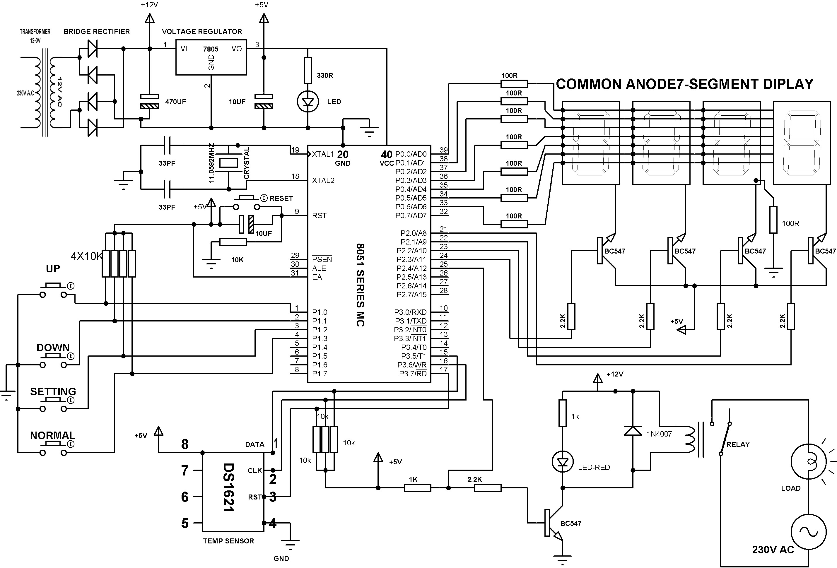
Precise Digital Temperature Controller Circuit Working And Its Applications

Closed Loop System Working Animation Process Control Understanding Loop
Precise Digital Temperature Controller Circuit Working And Its Applications
Precise Digital Temperature Controller Circuit Working And Its Applications
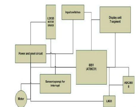
Temperature Controlled Fan Using 8051 Microcontroller

Remote Temperature Monitoring System System Pic Microcontroller Remote

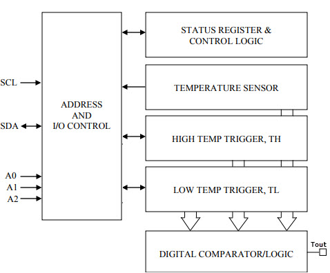
Ds18b20 Temperature Sensor Pinout Principle Circuit
Closed Loop Control System Block Diagram Types Its Applications

Lm324 Based Temperature Setting Controller Design Video
2

Circuit Diagram For Temperature Controlled System Control System Temperature Control System
Precise Digital Temperature Controller Circuit Working And Its Applications

Ds18b20 Temperature Sensor Pinout Principle Circuit

Lm324 Based Temperature Setting Controller Design Video
Precise Digital Temperature Controller Circuit Working And Its Applications
Ad590 Based Digital Temperature Control Device Design